 |
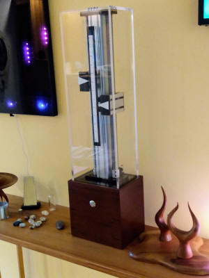
This is the eighth collaborative clock project that Dave and
I have completed. It is named after Dave's beloved dog
Lukie who died while we were making this piece. The
original idea began with some kind of vertical moving
components that would display time. In my research I
discovered these linear actuators that I found to be
intrinsically beautiful. In earlier design concepts,
they would have been hidden inside a base or pedestal, but
when we both saw them, it became clear that they should be
visible. Once we decided to use these, the design fell
together fairly quickly. One original concept was to
have large shiny ball bearings that would roll up and down
the outside of the case that would be held in place by
powerful magnets on the moving component. We
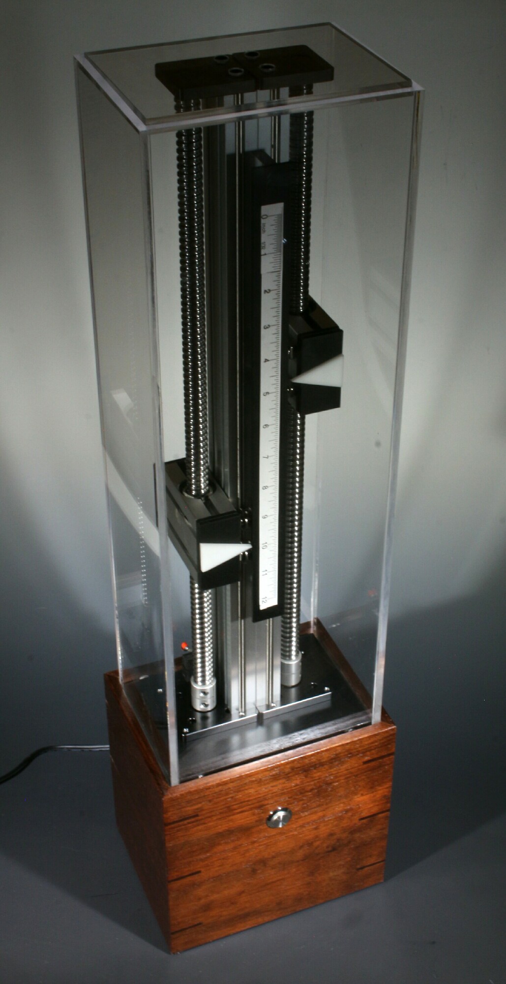
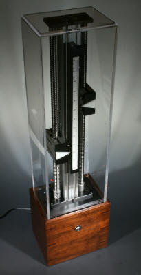
eventually decided to simplify it down to arrows that point
to a scale that is essentially a 12 inch ruler.
Time is interpreted by looking at the two arrows that are
pointing to the scale in the center that represents hours
and minutes. The left-hand pointer represents hours
and the right hand one indicates minutes. Both arrows
start at the top at 12 AM or p.m. and move down as time
progresses. At 12 PM the clock does a
performance where both arrows move all the way down to the
bottom making a subtle whining sound that is typical of
stepper motors. Then they move all the way to the top,
and finally each one moves down to the actual time
positions. I actually programmed speeds of the motors
to create interesting sounds as they move.
This clock is in constant but subtle motion as the motor on
the right moves in very small increments every minute.
Then when the minutes pointer has reached the bottom, it
moves all the way up to the top and the hour pointer on the
left moves down 1" to the next hour. |
|
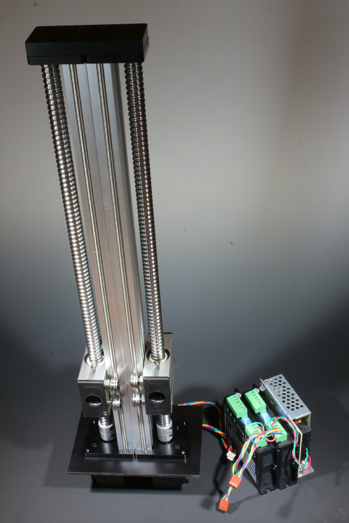
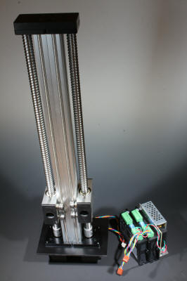
Shown at right are all of the functioning components of this
clock. There are two linear actuators driven by
stepper motors that are secured to each other with a top and
the bottom plate. |
 |
|
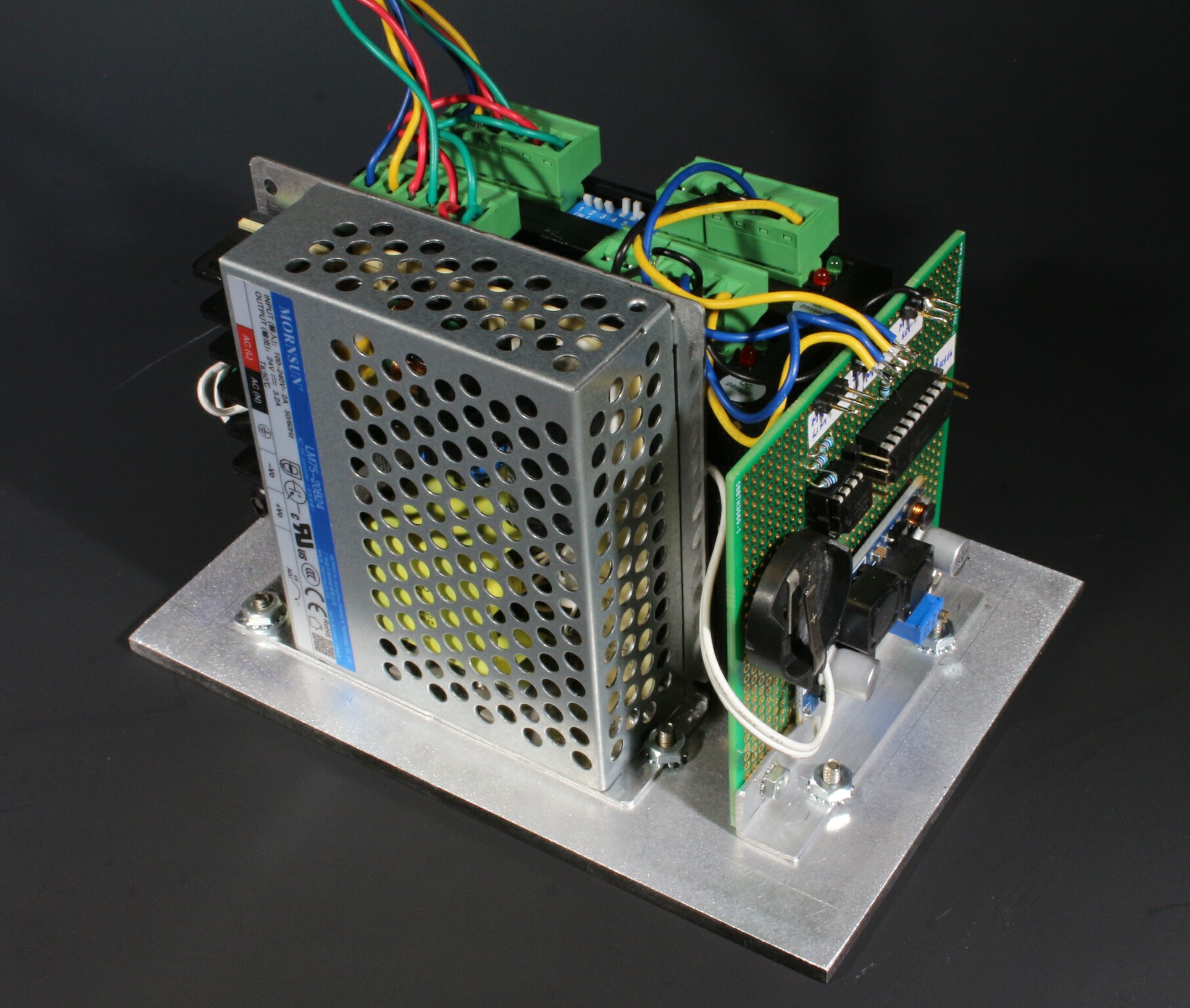
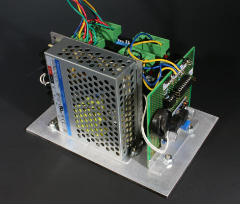
I was able to use largely off-the-shelf parts that include a
DC power supply and two stepper motor controllers. I
had to build a small control board shown on the right that
includes the microcontroller in real time clock circuitry.
all the parts are mounted to an aluminum plate that gets
mounted to the bottom of the wood case. |
 |
|
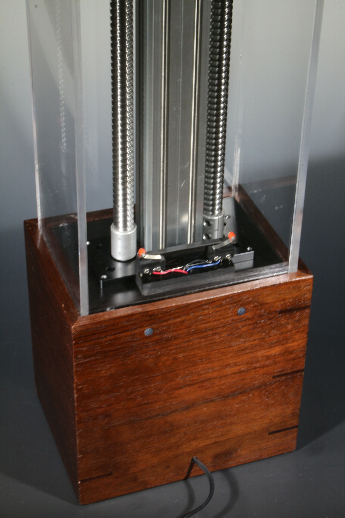
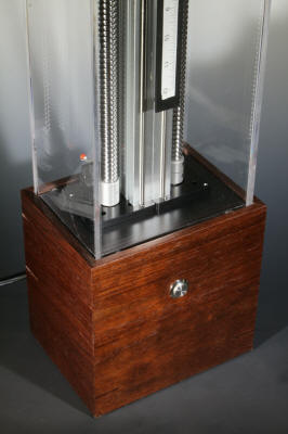
We brought in my friend John Rogers to make the wood base from walnut.
Then I mounted all of the parts to it including the button you press to trigger
a motorized performance which also serves to re-index and home the two stepper
motors. |
 |
|
I mounted two small gray buttons on the back that are used to set the hours and
minutes. the electronics include a real-time clock that remembers the time
even if the clock were to be unplugged for several days or months.
Visible at the bottom of the mechanism are two small switches. These are
used to sense the bottom position of the lead screws. Stepper motors
always require some kind of home/index position in order to determine relative
positions from there. |
 |
 |
|
After completing each piece, I get to keep it for a week or so to enjoy before I
send it down to Dave in North Carolina. I particularly enjoyed having this
clock around because of all of the fun little sounds and movements that it
makes. |