|
|
|||
| Product Design | My Artwork | Living Sustainably | |
| Art Engineering | Levitation Kit | Solar Power | Chevy Volt |
| About Me | Blog | Solar Heating | Thermal Windows |
| Contact | Solar Hot Water | Solar Mower | |
|
|
|||
| Product Design | My Artwork | Living Sustainably | |
| Art Engineering | Levitation Kit | Solar Power | Chevy Volt |
| About Me | Blog | Solar Heating | Thermal Windows |
| Contact | Solar Hot Water | Solar Mower | |
home > solar mower
CONVERTING A GAS LAWN MOWER TO
SOLAR CHARGED ELECTRIC POWER
| HOME | PARTS LIST |
REMOVING GAS ENGINE |
INSTALLING ELECTRIC MOTOR |
INSTALLING COMPONENTS |
WIRING THE MOWER |
MOUNTING THE BLADE |
SOLAR CHARGER |
TEST DRIVE |
OTHER CONVERSIONS |
|
Electrical wiring |
||
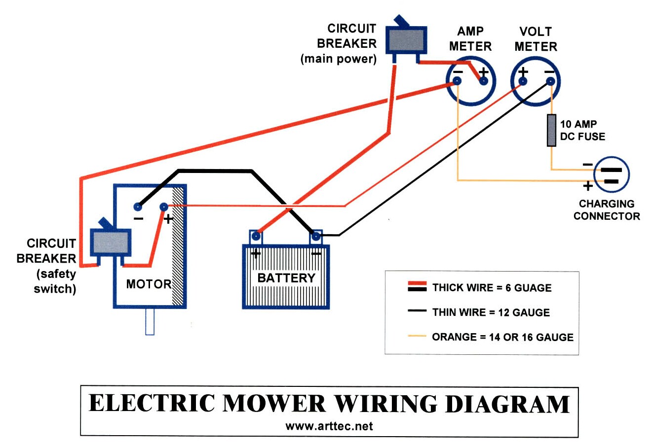 wiring diagram (157K printable size file)
|
Hooking up all this high current wire is daunting, even for an engineer
like me. I always start with a wiring diagram. It took me 3
tries to get this right, and I'm good at this! Click the image at
left for a printable sized (255K) schematic.
SAFETY FIRST! If you are not comfortable with high power wiring, then be sure to find some qualified help. An accident could short out the battery which could then explode and kill or seriously injure you! Be very careful! There are 3 circuit loops:
The big motor wires will be carrying up to 40 Amps and so must be 6 gauge, I recommend color coding the wire using red and black as appropriate (see my diagram). Charging current will be up to 6 Amps so a 12 or 14 Gauge extension cord will work fine. Wires to the Volt meter are also carrying charging current and so can be 12 Gauge stranded house wire (not solid wire - it will break!). Since wire lengths can't be determined until the parts are all located, I began by mounting everything securely to the mower. Vibration is an issue so I used lock nuts, lock washers or thread lock throughout to ensure that nothing works loose. |
|
 |
Here is the mower before wiring. All the components are in place: motor, circuit breaker, battery, and the gauges on the handle bar. | |
 |
I obtained 8 #6 ring terminals from Home Depot when I picked up the wire. They should be crimped firmly, soldered and then insulated. I don't have a crimping tool that big, so I mashed it with a hammer! Soldering with a 240 Watt gun takes several minutes to heat up the wire until the solder flows into the lug and fills it. One could also use a small propane torch, but at the risk of badly melting the insulation. The final touch is heat shrink tubing - or wrapping it with insulating tape. Try to cover up as much of the exposed metal of the lug as possible with insulation. |
 |
|
NOTE! When using tools around a battery, be VERY CAREFUL not to drop a tool so that it falls across the battery terminals! It will weld itself across the battery, shorting it out and will cause the battery to EXPLODE. An exploding battery will spray acid everywhere and could kill or seriously maim you. A good precaution is to wrap tool handles with electrical tape, and always keep at least one battery terminal covered with an insulator like a plastic cup. Safety first! |
||
 |
I started with the small 12 gauge stranded wire to the meter, and worked my way up to the motor, breaker and battery. I made the last connection the battery positive (+) terminal for safety, In case I messed up! I left enough loose wire to allow for the movement of the handle. |
 |
|
|
I decided to use a computer power connector for the charging jack because the end of the cable has good insulation around it's connections. I was worried about using a male AC plug because the exposed prongs would be carrying 12VDC from the charger that could get shorted and blow the fuse on the charge controller. |
 |
 |
Here are some views of the completed wiring. Note the extra circuit breaker on the right that I added. I was concerned that I might accidentally bump the safety handle and start the mower, so the extra switch is a main power switch wired in series with the Amp gauge. |
 |
.JPG) |
UPDATE June 2016. I replaced the old analog Volt and Amp meters with a new digital display that shows Volts, Amps, Watts and Watt hours consumed. More details about this on my blog. And here is the manual for the meter showing where I bought it. |
 |
|
|
| HOME | PARTS LIST |
REMOVING GAS ENGINE |
INSTALLING ELECTRIC MOTOR |
INSTALLING COMPONENTS |
WIRING THE MOWER |
MOUNTING THE BLADE |
SOLAR CHARGER |
TEST DRIVE |
OTHER CONVERSIONS |

